Multi-stage Vertical Frac
Multi-stage Vertical Frac Video
Multi-stage Vertical Fracking Video | John Perez Graphics – Federal Copyright # PA 1-723-565
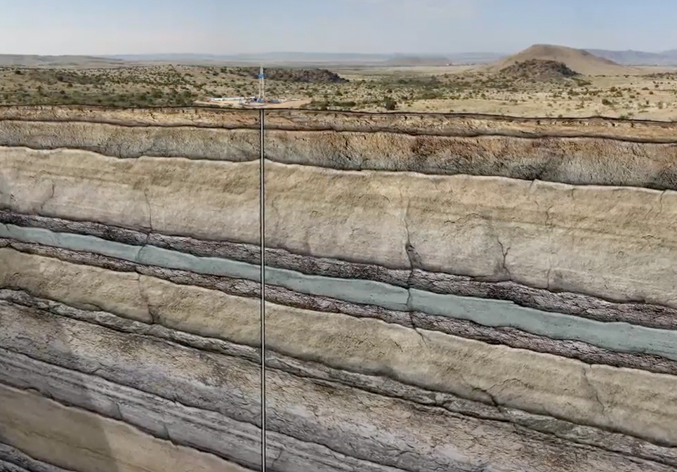
There are many formations with multi-zone oil and gas reservoirs that are vertically drilled and stimulated using hydraulic fracturing to optimally recover these hydrocarbons. In this example, we show a well targeting three sandstone layers, although this number may vary in different oil and gas plays. Once the drill rig and other infrastructure is in place, a bit mounted on the end of the drill pipe begins drilling the well. The well is initially drilled to a designated distance below the deepest fresh water source near the surface. The pipe and bit are then removed, and surface casing is inserted into the hole. The casing is then secured into place by pumping cement through the casing and through the shoe at the bottom of the hole. The cement barrier and steel casing prevent any contamination of freshwater aquifers.
Once the casing cement has set, drilling of the intermediate section of the hole continues by drilling through the wiper plug, shoe, and cement at the bottom of the wellbore and on toward the targeted zones. Throughout the drilling, a mixture called “mud” is pumped down into the well through the drill pipe. The mud serves to keep the drill bit cool. It carries the cuttings to the surface, and provides hydrostatic pressure, prohibiting formation fluids from entering the wellbore. As drilling approaches the depth of the first target zone, a technician called a “mud logger” is brought on location. He analyzes the cuttings, identifying the down hole lithology, and any presence of hydrocarbons. As the well is being drilled, he provides real-time information to the company geologist and rig personnel. Once the bottom of the intermediate section is reached, the drill pipe and bit are again removed from the wellbore, and intermediate casing is inserted into the hole and connected to the surface casing.
The intermediate casing is also cemented to secure the hole. The drill pipe and bit are again lowered back into the hole, and drills through the wiper plug, shoe, and cement. Once total depth is reached, the drill pipe and bit are removed from the wellbore one last time. Next, a logging tool is lowered to the bottom of the well on a wireline. As the tool is pulled back up the entire length of the well, data is gathered to create an electric log. Once the well has been logged and deemed a commercial well, production casing is then inserted. As with the surface and intermediate casing, the production casing is also cemented into the hole. Back on the surface, the drilling rig is no longer needed. A temporary wellhead is installed, and the location is prepared for the service crews who will ready the well for production.
The first of these steps is to perforate, or “perf” the casing. A perforating gun is lowered by wireline to the lowest of the three target zones. An electrical current is sent down the wireline to the perf gun, setting off a charge which shoots holes through the steel casing, cement, and out a short distance into the target formation. The perf gun is then pulled out of the hole. The next step is to hydraulically fracture, or “frac” the zone. Here, sand, or other proppants are pumped into the wellbore under extremely high pressure. When the mixture reaches the target zone, the pressure forces it out through the perf holes and out into the sandstone formation, causing it to fracture. This creates a fairway connecting the reservoir to the well and allows the released oil to flow to the wellbore. Next, a bridge plug is placed inside the production casing, isolating the fracked zone. The hydraulic fracture process is then repeated for zones two and one. Now that the frack process is complete; the plugs are drilled out and production tubing is lowered into the wellbore to reach each of the productive zones.
Hydrocarbons can now flow simultaneously from each of the zones into the well. The next step is to install a permanent well head and other necessary surface equipment. Sometimes a pumpjack is used to help bring the oil to the surface. The final step is to install and connect a pipeline to the well that will transport the oil to the nation’s pipeline network. Wells that produce from several zones simultaneously result in greater cost efficiency, and increased productivity.
Other Educational Animations
Multi-stage Vertical Frac

This Multi-Stage Vertical Frac Crude Oil Animation explains and demonstrates how a vertical well is drilled, stimulated and produced from multiple formations to recover hydrocarbons. In this animation, we show a well targeting three sandstone layers. The well is initially drilled to a designated distance below the deepest fresh water source near the surface.
Impact Crater

The 10 biggest impact craters on Earth date back from 35 million to over 2 billion years ago.
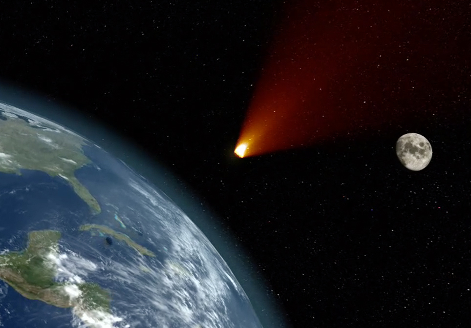
When an asteroid or meteorite crashes into the surface of a planet or a moon, a circular depression is formed. To form a true impact crater, this object needs to be traveling at super-fast speeds – many thousands of miles per hour! It immediately vaporizes and creates enormous shockwaves through the ground that melt and recrystallize rock and are one of the most destructive forces in the solar system.
The Chicxulub crater, sometimes referred to as the deadliest location on earth, is buried beneath the Yucatán Peninsula in Mexico. When the Chicxulub asteroid slammed into Earth about 66 million years ago, it obliterated 80 percent of Earth’s species, blasted out a crater about 200 kilometers (124 miles) across and 19 kilometers (12 miles) deep, and signaled an abrupt end to the Cretaceous Period.
CO2 EOR Carbon Dioxide Enhanced Oil Recovery

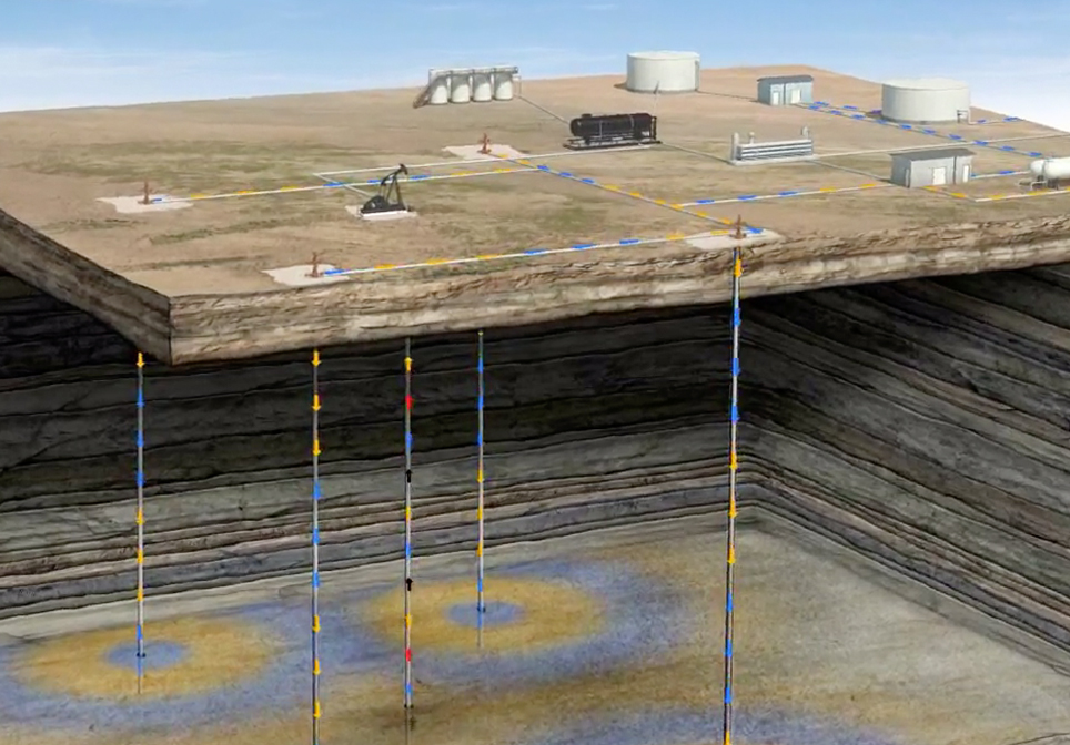
This CO2 EOR Educational Animation – created by John Perez Graphics & Design, LLC – explains the CO2-EOR process. We travel deep in to the Earth’s subsurface to demonstrate injection, miscibility, WAG, and increased oil production.
Saltwater Disposal

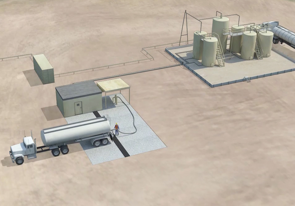
This Saltwater Disposal Well Animation – created by John Perez Graphics & Design, LLC – explains the steps necessary when disposing of salt water that is produced when drilling an oil or gas well. The animation takes you from the surface facilities, through the various protective casing strings down several thousand feet to the pre-approved formation zone where the salt water will be disposed of. This follows the EPA preferred method for the disposal of produced saltwater in Class II Saltwater Disposal wells.
